Building a vacuum tube computer

|
Vacuum tube computers haven't been built for 50 years, so I thought it was time to do it again.
A design goal is to only use technique from around 1950. That means vacuum tubes for all logic in the CPU, no semiconductors except for crystal diodes (patent from 1906, commercial germanium diodes in the 40's). The plan is to implement an existing architecture, and here the conclusion has come to the Berkeley RISC-V. It has only 37 instructions in its RV32I description, is very clean and simple in design and there are test programs and software available. Another goal is to construct the computer using a cycle time of 1us (1MHz), to get a reasonable speed. Some mixed (calculated) specifications (2015-01-30)
Drawings Reference litterature |
2018-04-23 5-to-32 decoderFor register decoding an efficient decoder is needed. In sequence, the decoder will be driven from a multiplexer which multiplexes the three inputs from the register parts in the instruction plus the refresh counter. Since it will decode which row in the register storage that will be addressed, all outputs are needed.There are a number of ways to do this. The most obvious way would be to use diode matrixes, but that would mean a load with up to 10 diodes per driver tube in the multiplexer. Total use would be 160 diodes. A simpler way would be to use a diode pyramid. That would be fewer diodes (124), but a more complex design that will increase the propagation delay. Another quite different 2017-12-13 Timing and contact-point diodes in capacitor storage arraysThe design of the CPU uses a cycle time of 1us, and one instruction is expected to take 8 cycles. Since the refresh rate need to be quite high, the plan is to execute a refresh cycle each time an instruction fetch is executed. A refresh cycle (or readin/out cycle) is designed to take 1us, but the cycle thereafter will be a "settling" cycle when the logic goes back to normal.Having 32 (31) registers, this means that a refresh will be issued each 256us. To be on the safe side, the capacitor should keep its charge much longer than that. Testing with both EAA91 (ideal diode) and some semiconductors:
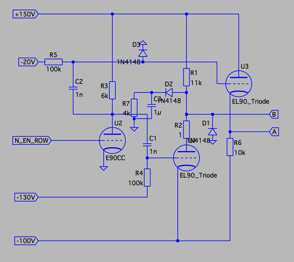
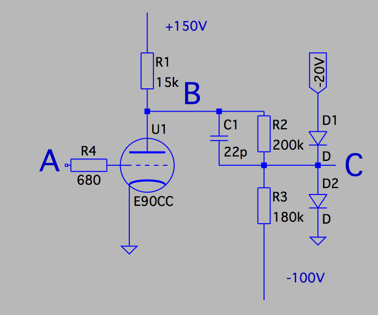
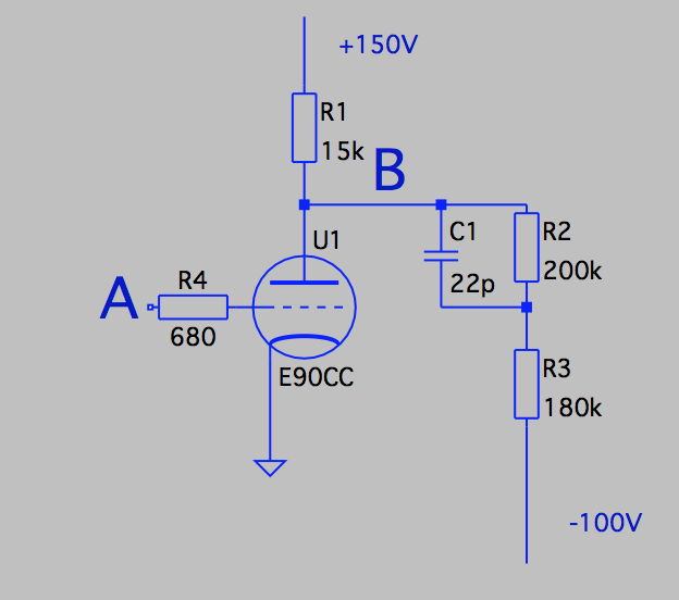
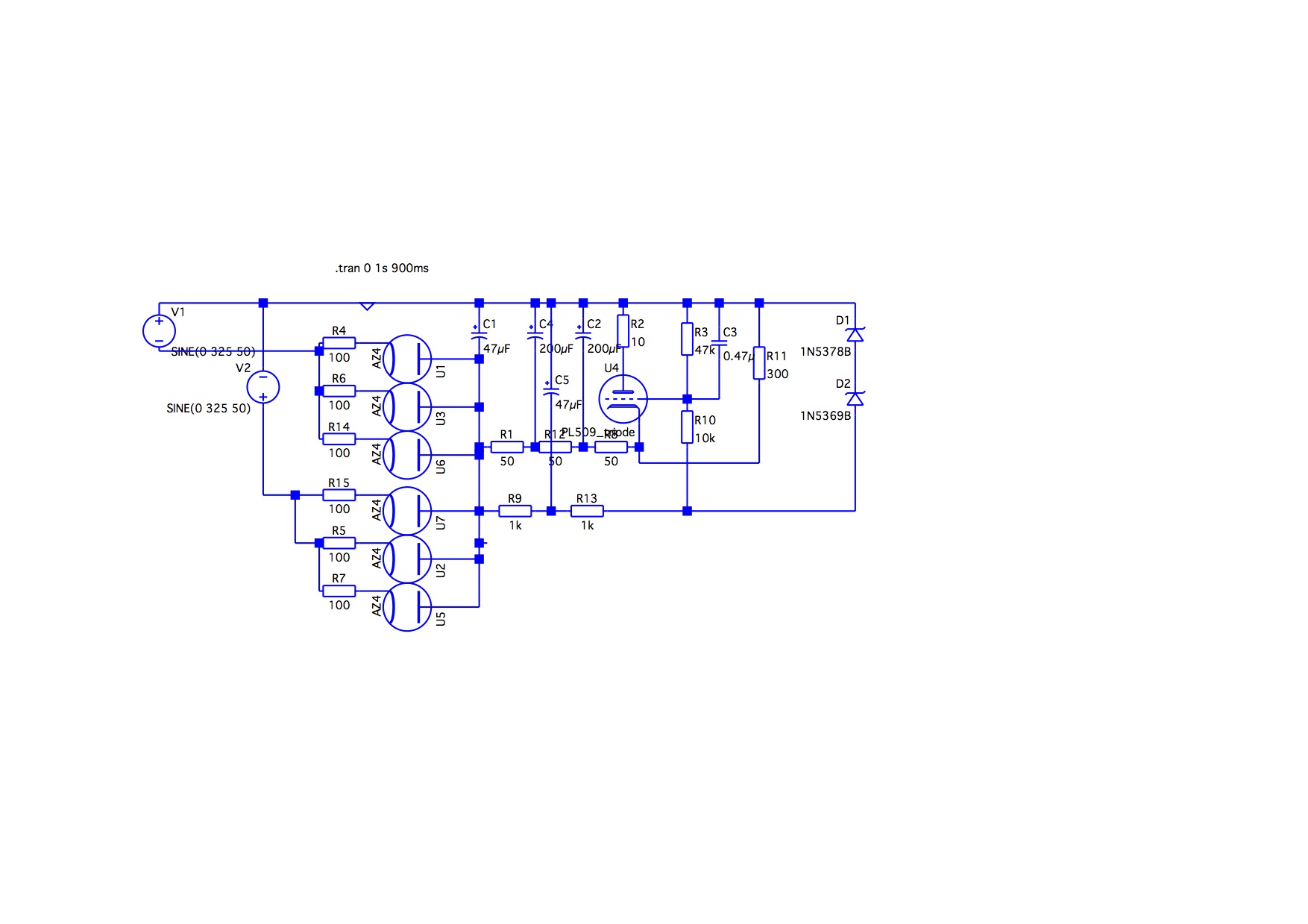
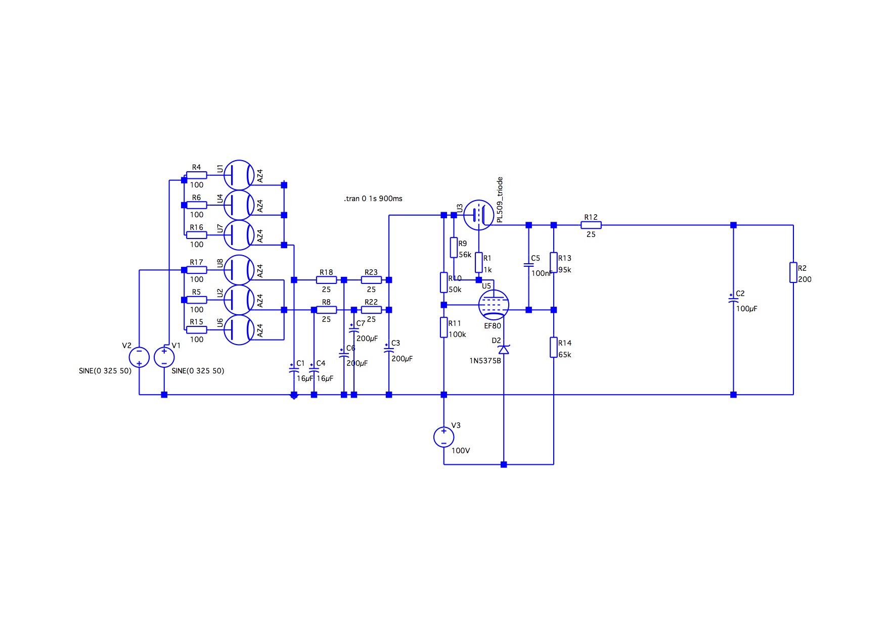
2017-11-19 Vacuum-tube DRAM arrayThe implementation of the register storage will consist of three separate parts of logic. Here we end up with a design that is quite similar to how DRAM logic works, with the main difference that we use two diodes instead of a transistor to address one bit.
 The capacitor is loaded with 40V when storing a '1', and unloaded for '0'.
When idling, the diodes are having approx. 40V in the non-conducting direction,
hence causing the left end of the capacitor to float. When the data should be
read-out, U1 and U3 in the row logic will be activated and work "against" each other.
This will cause the storage capacitor to give a pulse out if loaded.
The capacitor is loaded with 40V when storing a '1', and unloaded for '0'.
When idling, the diodes are having approx. 40V in the non-conducting direction,
hence causing the left end of the capacitor to float. When the data should be
read-out, U1 and U3 in the row logic will be activated and work "against" each other.
This will cause the storage capacitor to give a pulse out if loaded.
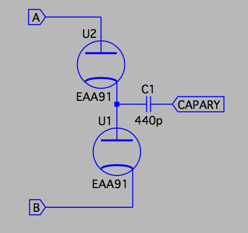
We are now down to a use of 78 tubes in the row logic and 112 in the column. Besides that, diodes are needed for the capacitor arrays, which would be 992 tubes using EAA91. This is still a large amount of tubes, but using quad-diode tubes like 6JU8 would cut that amount in half. 2017-09-09 Using capacitors for register storageOne of the big problem in designing a vacuum tube computer is that flip-flops are quite expensive circuit-wise. A traditional flip-flop will take (at least) two tubes, and for a 32-bit CPU with 31 registers this will use 1984 (!) tubes for the register file alone.This is an unreasonable amount of tubes just for the register file, which also reflects the design of computers at that time. The IAS architecture usually had only one or two registers for calculations.
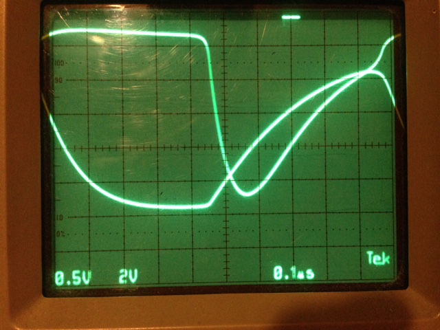
I did setup a simple test bench to just see if it would be reasonable to do something with capacitors, and it worked quite well. The resistor R3 is used to simulate leakage, and U2 is used to have a high-impedance input with oscilloscope connected to its cathode. 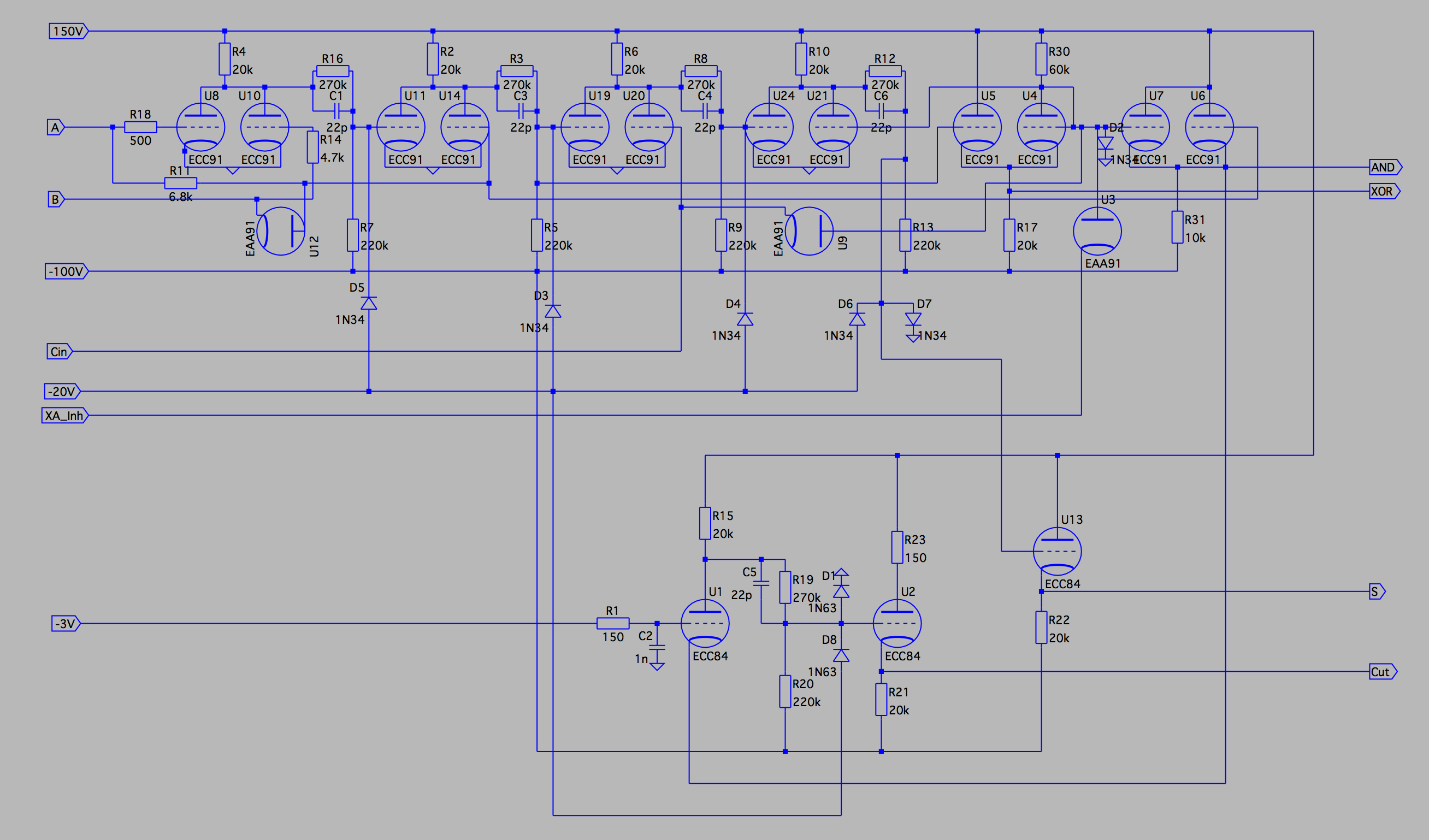
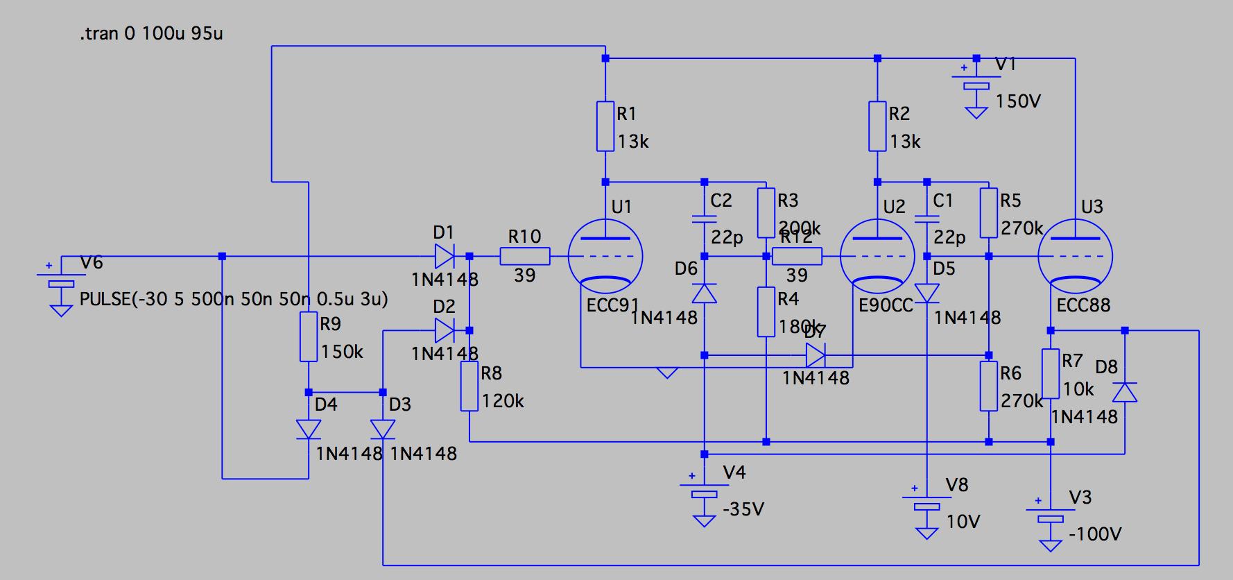
2017-01-14 Building an ALUThe ALU designed has five functions (ADD, SUB, AND, OR, XOR) of which three are main functions and two implicit which will be described later on. Of the main functions the complex part is ADD. As well-known when it comes to adders, the carry propagation delay may be significant, therefore this adder tries to minimize the propagation time which may be substantial in inverters (see below).Missing here is the left/right shift parts which are usually part of the ALU. They are not included here because the logic is very different from what is used here, and since it will be an implementation that is similar to a barrel shifter a substantial amount of logic will be needed for itself. The basic logic design of the adder is a schoolbook example of how to build a full-adder, and a large part of the circuit design comes from the BESK Computer but with some modifications to speed up the circuits and lower power consumption. The output signals for AND, XOR and Sum are intended to drive a diode and/or MUX, hence the signals uses cathode followers to handle the load. By using this logic we can get the OR function by selecting both AND and XOR in the diode MUX, so no extra logic is needed. To get correct AND/XOR (and OR!) output signals the signal XA_Inh must be held low for these functions.
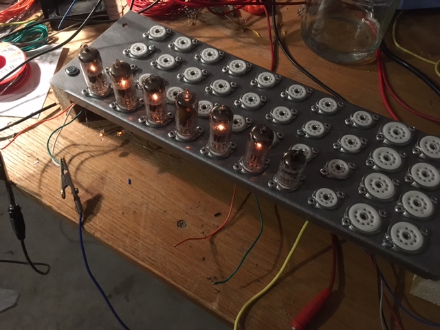
Carry logic deserves a separate description. The propagation path through the adder uses only diode logic and cathode followers to minimize the delay, but a side effect of this is that we will lose signal voltage (since μ of a cathode follower is less than 1). Therefore carry out of three adders are the same as the AND signal, but the fourth will feed a signal restore circuit, U1 and U2 in the drawing. The total propagation delay for four bits will be less than 50ns in theory, which is 400ns for a full word and much less than the cycle time of 1us that is intended to use. The picture shows a 4-bit ALU during test of one bit. 2016-10-12 Speeding up gate delaysTo avoid the problem with capacitances in the circuits the common way has been to lower the resistance and increase the current; this is true today as well. This has the side effect of consuming more power and exposing the whole system to stress and to require more cooling. But there are other ways of achieving a similar result. From the description below, as well as the oscilloscope picture, we can see that the anode voltage pretty much follows the ln curve, which takes some time, especially at the last volts which is when the following tube is turned on. We can note that the voltage swing is quite large, around 100V at the anode, which gives about 50V in the voltage divider to the following grid. This is much more than needed, the cutoff voltage for the following tube should be around -8V for this type of tube.
Clamping the circuit will be especially effective on a positive-going pulse since the voltage rise distance will be much smaller. Carefully designed circuits may get down to a gate delay of less than 30ns by only using this technique. Circuit designers should note though that the value of C1 may need to be altered, since it act as a reactance divider together with the control grid input capacitance (and Miller effect).
2016-09-11 Vacuum tubes and gate delayThe gate delay in vacuum tube logic circuits has historically been rather long, so I'll try to explain here what happens. First; there are two laws of nature that could affect tube logic. One is the fact that all wiring is longer which forces the electrons to travel a longer distance. This may or may not affect the circuit; but electron speed in cupper is about 15-20cm per nanosecond so it is usually not a big factor. The other is the electron leap time through the tube. An electron must first be excited so that it leaves the cathode, then travel through the tube to the anode. This can usually be ignored in computer applications since the tubes used are designed for this type of usage. On the other side, there are no such things like reverse recovery or voltage drops in vacuum tubes, so from this perspective they are ideal.
The input time constant will be 78.4*10^-12*680=53ns. With voltages between 0 and -20 this means that on the falling edge cutoff will be reached after t=-ln((V-Vc)/V)*τ, which will be around 20ns. On the rising edge it will reach conducting close to τ, so say 55ns. High input capacitance is also a problem for HF amplifiers. The Miller capacitance can be avoided by using pentodes, which have a much lower anode-grid cap. Also, the input resistor can be of a lower value, but at the cost of a more unstable circuit (it's task is to prevent oscillation).
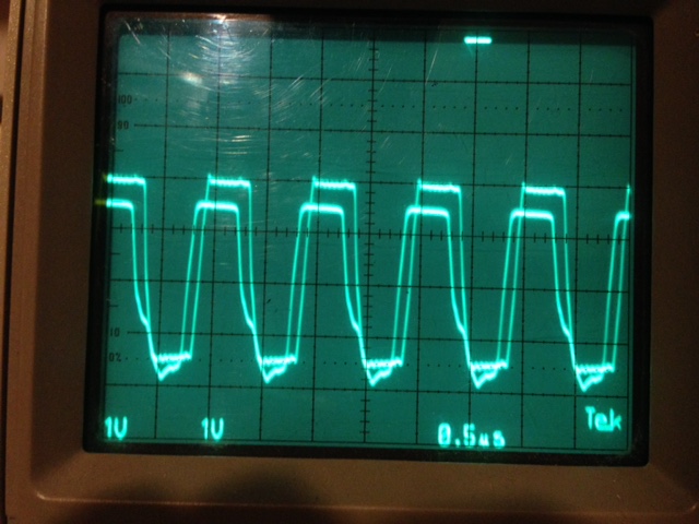
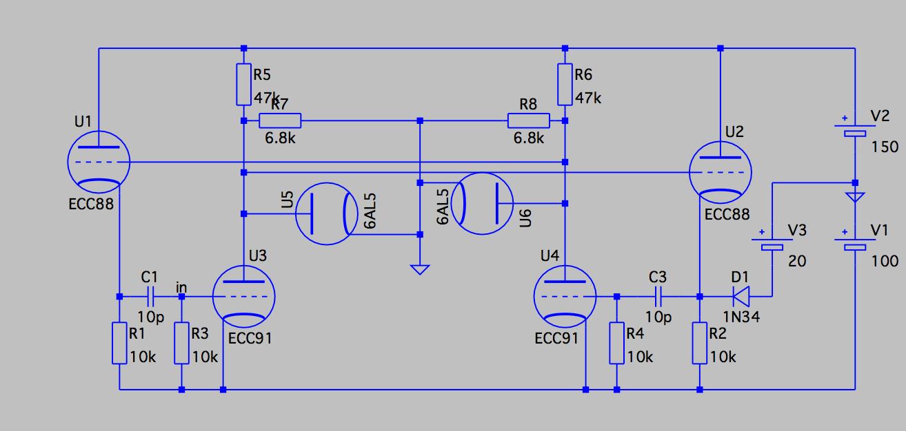
As a total this adds up to around 20pF. When the tube is cutoff the resistance is mostly the anode resistor which gives a τ of 20pF*15kohm = 300ns. Looking at the picture we can see that it is rather close to reality; it is 20V/square, curve starts at 43V and (should) go up to 150V. After 300ns the curve is at 105V as it should (43+63=106). We also note that the falling slope of the anode is much steeper than the rising. This is because the anode resistor now is in parallel with the anode resistance of the tube (since it is fully conducting). The anode resistance is 4kohm in the E90CC, but the calculations is left to the reader :-). 2016-08-14 Flip-flops and cathode followersAs mentioned below, astable and bistable flip-flops have the same issues. One of the problems is that the circuit must be very well balanced, otherwise the the circuit may flip back erroneously, for example due to a rising edge on the input capacitor after an earlier flip.There were a number of different solutions to this, but most of them involves cathode followers. MIT used a version in Whirlwind (stated up to 4MHz), which was driven by pentodes and pulse transformers. IBM instead used crystal diodes to gate the feedback driver signal from the cathode follower to the input control grid. I made a drawing which use diode gating logic in the same way as IBM, but to avoid too much rise-and-fall time the input signals were clamped between +10V and -30V. The result was very good. Connecting both the set and reset signals to output from the multivibrator below can be seen on this oscilloscope picture with the input and output curve on top of each other. Most notable is that the gate delay for the latch is very close to 100 nanoseconds, which should be considered veey good. Also note that the malformed curve (at the bottom) is from the multivibrator where the output signal is not clamped. The latch output is much more "square-formed". Another interesting thing is the blurriness on both the top and the bottom of the latch output. This is due to reverse recovery in the 1N4148 diodes I used here. I have observed earlier that using the 1N34 crystal diodes instead do not result in nearly as much reverse recovery behaviour. 2016-08-14 Clock pulse generator designAs one of the initial design goals was to have a cycle time of 1 microsecond, a high-speed astable multivibrator had to be designed. The problems that arises are the same for astable and bistable Eccles-Jordan multivibrators, and can be avoided in the same way.Mainly three different problem arises when the speed of a multivibrator increases.
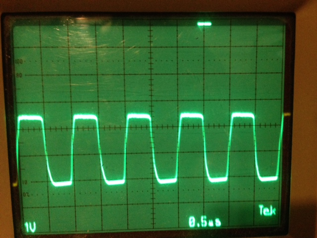
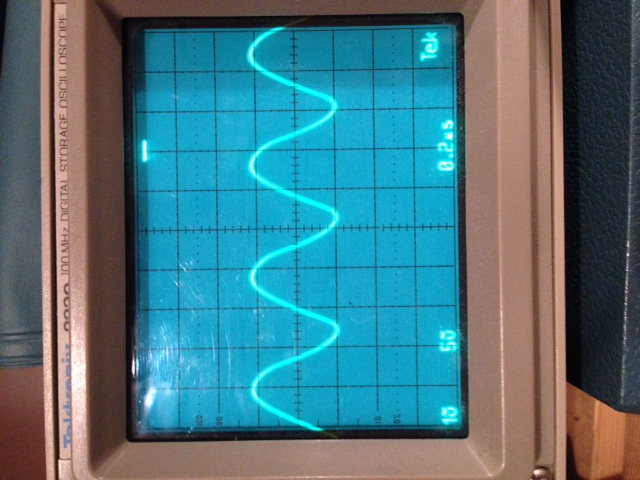
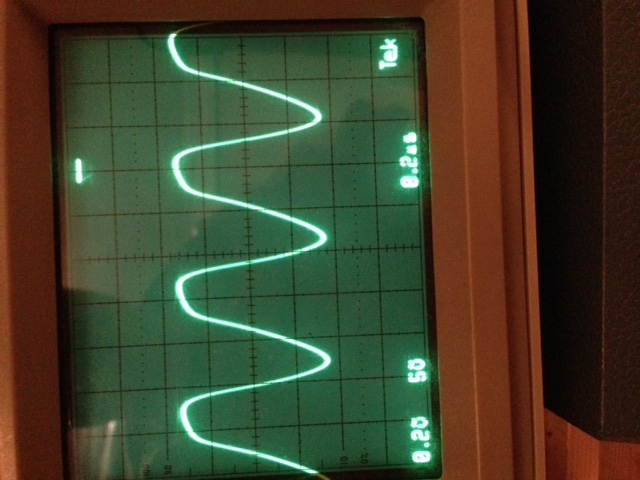
Some discussions on the subject of multivibrators, including implementations, can be found in Digital Computer Components and Circuits which is a very good source of 1950's computer design issues. 2015-01-02 Astable Multivibrator RevisitedAfter a long pause it was time to put the dust of some multivibrator implementations to see in which direction to go. The tests were done with both an Abraham-Bloch and a Schmitt multivibrator. Both were tested with a 6J6 and an E90CC tubes.The result were that it was much more difficult to get Schmitt behave correctly. Also there were difficulties to trim the multivibrator for higher speeds. With 6J6 it was possible to get a cycle time of 500ns. The behaviour of Abraham-Bloch was much better. Here it was also possible to get 500ns intervals with 6J6, but E90CC could easily be run down to 200ns, which is quite good. Since the intention is to have a cycle time of 1us, there is a lot of "spare time". It can also be noted that the curves come closer and closer to sine wave, but the real interesting time here is the slope fall time, since it will be used to trigger flip-flops. The curves measured as of below o the control grid. Note that they are probably uglier than expected, 10pF in the oscilloscope probe may affect some.
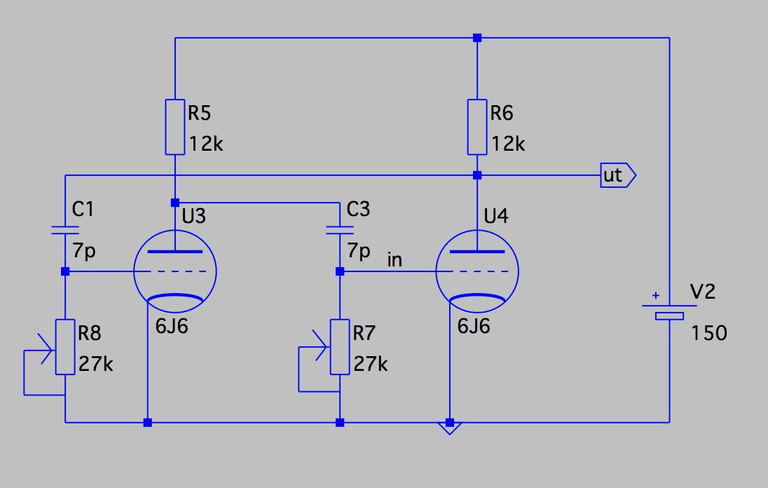
2014-03-18 Full adder simulationI did a trivial implementation of a full adder implementation using only 6J6 and 6AL5 to see the resulting behaviour and latency through the adder. The number of tubes used are excessive, 12 of them, but it is how they act that is interesting. Also some pulse shapers would be good to add, but not important here.The schematics are here and the simulated latency here. This became a quite complex adder, with the pulses passing through 10 tube functions for the sum output and 7 for the carry output. Nevertheless, the total delay is very low, for carry out it is 80nS for low-going signals and effective 0 for up-going. For the sum it is just over 100nS in both directions. The quick response to the signals are due to the use of cathode followers, which have a very short switch time. The inverters introduces more delay to the system. Another (unpleasant?) side effect of the large use of cathode followers are the large amount of current the system uses. For this full adder the current ends up between 60-100mA. 2014-01-15The tests (both simulation and real tests) of the tubes went reasonably well. At least the 6J6 tubes are quite usable, so I ordered 2000 5J6 tubes and 1000 3AL5. 5J6 is a 6J6 (double-triode) but for serial coupling, and 3AL5 is a dual-diode for the same use.An interesting note here is that the 5J6 tubes did not behave as expected with the filament voltages. At 4.7V filament voltage the current were only about 300mA and emission much lower than expected (around 50-70% of nominal value). Increasing voltage to 6.3V gave a filament current of 450mA, which exactly matches 6J6 (!). Also the emission came up to expected levels. So it seems like "mis-marked" 6J6... 2013-11-25Written a small program I called kurvmatch that can generate SPICE models for vacuum tubes. There were a bunch of people that already had done things like this, but they used matlab or similar programs which I didn't have at hand. Now it is a quick process to add models for the uncommon tubes that will be used in the computer.2013-11-10A power supply for 150V made from an old radio, using AZ1 as rectifier and 0A2 as voltage stabilizer. An astable multivibrator built and output waveform checked. Result is that down to 2us pulse intervals the square wave is quite good, then it degenerates quickly to a saw-tooth-formed wave at highest speed with an interval around 600ns. This seems to be due to the Miller capacitance.2013-08-16Ordered 10 6J6/ECC91 and 20 6CS6/EH90 to do some real testing. The test bed setup will consist of an astable flip-flop to generate clock pulses and one register bit. It will be really interesting to see what the quality and delay of the signals will be after they have passed through this! |

